247851_DPC front Standard_d.pmd
advertisement
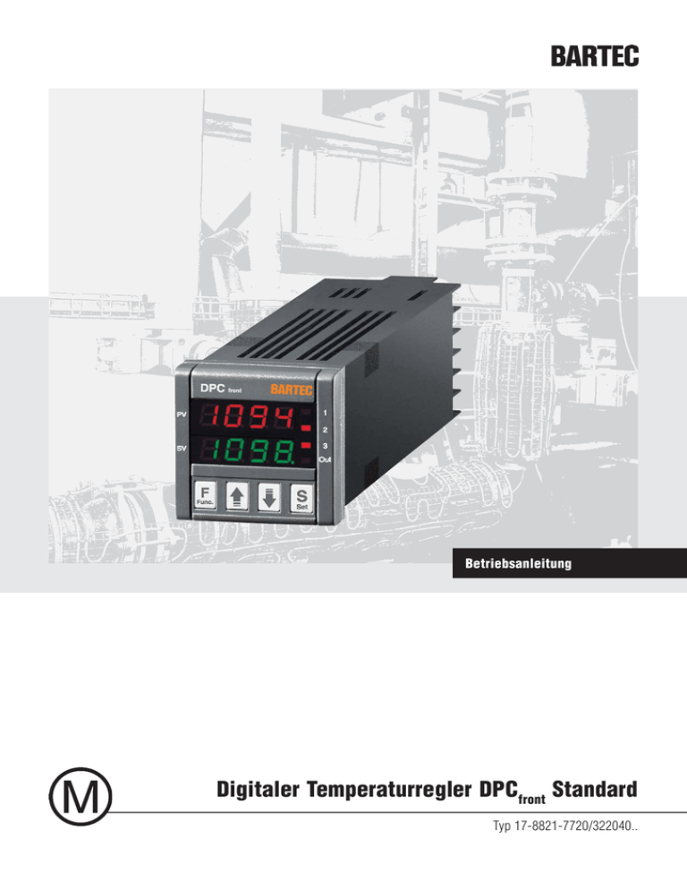
Betriebsanleitung Digitaler Temperaturregler DPCfront Standard Typ 17-8821-7720/322040.. Vorbehalt Technische Änderungen behalten wir uns vor. Änderungen, Irrtümer und Druckfehler begründen keinen Anspruch auf Schadensersatz. Inhalt 1. Bestimmungsgemäße Verwendung 2 2. Produktbeschreibung 2 3. Sicherheitshinweise 3 4. Erstinbetriebnahme 3 5. Montage und Inbetriebnahme 3 6. Betrieb, Wartung 4 7. Alarmmanagement 4 8. Technische Daten 4 9. Elektrische Daten 4 10. Elektrischer Anschluss/Geräteanschlüsse 5 11. Parameterliste 5 12. Störungsmeldungen/Störungsbeseitigung 6 13. Typenschild 6 14. Abmessungen 6 15. Montageausschnitt 6 16. Serviceadresse 6 1 DPCfront Standard Typ 17-8821-7720322040.. 1. Bestimmungsgemäße Verwendung Betriebsanleitung 2.2. Frontansicht Der digitale Temperaturregler DPC front dient zur Temperaturregelung explosionsgeschützter oder mediensicherer Heizungen bzw. Heizkreise. Der DPC front ist stets außerhalb des explosionsgefährdeten Bereichs zu installieren. Bei seiner Verwendung ist zu unterscheiden zwischen: LED AT a) der Überwachung explosionsgeschützter Heizkreise: Der DPCfront wird zusammen mit dem Widerstandsthermometer Pt100 Ex (Typ 27-71..-.3.. ....) verwendet. Display PV (Process value) LED Out2 Display SV (Setting value) b) Überwachung nicht explosionsgeschützter Heizkreise: Der DPCfront wird zusammen mit einem mediensicheren Pt100-Widerstandsthermometer verwendet, z. B. Pt100-Widerstandsthermometer Art.-Nr. 03-9040-00... Taste S (Set) Taste DOWN Taste UP Taste F (Func) 1.) Taste S (Set): Zugriff auf den Programmiermodus der Schnelleinstellung und zur Eingabebestätigung. 2.) Taste DOWN : Mit dieser Taste wird der einzustellende Wert reduziert. Wird die Taste gedrückt gehalten, geht man zur vorangegangenen Programmierebene zurück, bis der Programmiermodus verlassen wird. 3.) Taste UP : Mit dieser Taste wird der einzustellende Wert erhöht. Wird die Taste gedrückt gehalten, geht man zur nächsten Programmierebene über, bis der Programmiermodus verlassen wird. Befindet man sich nicht im Programmiermodus, wird anhand dieser Taste die Regelleistung am Ausgang angezeigt. 4.) Taste F (Func): Deaktivierung/Aktivierung der Regelung durch längeren Tastendruck 5.) LED Out1: Signalisiert den Zustand des Ausgangs OUT1 6.) LED Out2: Signalisiert den Zustand des Ausgangs OUT2 7.) LED Out3: Signalisiert den Zustand des Ausgangs OUT3 8.) LED AT: Signalisiert, dass AUTOTUNING gerade läuft. 9.) LED SET: Signalisiert den Zugriff auf den Programmiermodus. 2.1. Allgemeines Der digitale Temperaturregler DPCfront Standard ist ein mikroprozessorgesteuerter „ single loop“ Digitalregler, mit Regelung EIN/AUS (Zweipunktregler) und PID und mit den Funktionen AUTOTUNING sowie automatischer Berechnung des Parameters FUZZY OVERSHOOT CONTROL für die PID-Regelung. Die PID-Regelung des Gerätes verfügt über einen besonderen ZWEISTUFIGEN Algorithmus, der die beiden Regelwirkungen unabhängig voneinander bei Prozessstörungen oder Änderungen des Sollwertes optimiert. Der Regler ist als EIN/AUS Regler vorparametriert. Die Umprogrammierung als PID Regler ist jederzeit möglich. Der Istwert wird im 4-stelligen, roten Display, der Sollwert im grünen Display angezeigt. Die Statusanzeige der Ausgänge erfolgt über LED’s. Im Gerät können bis zu 4 Sollwerte gespeichert werden. Der DPC front verfügt über 2 Relaisausgänge und einen Spannungsausgang zur Steuerung von Solid State Relais (SSR). LED Out3 LED SET Grundsätzlich ist das Widerstandsthermometer mechanisch und temperaturstabil an dem zu messenden Punkt zu befestigen, um die sichere thermische Kopplung zu gewährleisten. Dies sollte mit Hilfe von entsprechend temperaturbeständigem Aluminiumklebeband oder ähnlichen Materialien erfolgen. 2. Produktbeschreibung LED Out1 10.) Display PV (Process value): Zeigt den Istwert an. 11.) Display SV (Setting value): Zeigt den eingestellten Sollwert an. 2 DPCfront Standard Typ 17-8821-7720322040.. Betriebsanleitung 3. Sicherheitshinweise 4. Erstinbetriebnahme Bitte vergewissern Sie sich vor Inbetriebnahme, dass der DPC front gemäß seiner Kennzeichnung für den vorgesehenen Einsatz geeignet ist. 4.1. Allgemeiner Hinweis Für elektrische Anlagen sind die einschlägigen Errichtungs- und Betriebsbestimmungen zu beachten (z. B. Reihe DIN VDE 0100 oder weitere relevante nationale Bestimmungen). Es sind alle allgemeingültigen gesetzlichen Regeln und die sonstigen verbindlichen Richtlinien zur Arbeitssicherheit, zur Unfallverhütung und zum Umweltschutz einzuhalten. Erfolgt während der Schnelleinstellung in der Parametrierebene über eine gewisse Zeit keine Tastenbestätigung, so wird die Parametrierebene automatisch verlassen, und die Anzeigen wechseln in die Grundeinstellung zurück. 4.2. Schnelleinstellung des Sollwertes Taste S (Set) betätigen Im Display PV blinkt die Anzeige „SP 1“ (Sollwert 1) Im Display SV ist die Werkseinstellung des Sollwertes ersichtlich. Taste UP oder DOWN betätigen. Durch die Taste UP kann der Sollwert erhöht, durch die Taste DOWN kann der Sollwert verringert werden. Taste S (Set) betätigen Speicherung des neuen Sollwertes. Gleichzeitig wechselt die Anzeige im Display PV zu „AL1L“. Nun kann der Sollwert für den Tiefalarm eingestellt werden. 4.3. Schnelleinstellung des Tiefalarmes Taste UP oder DOWN betätigen. Durch die Taste UP kann der Sollwert erhöht, durch die Taste DOWN kann der Sollwert verringert werden. Taste S (Set) betätigen Speicherung des neuen Sollwertes. Gleichzeitig wechselt die Anzeige im Display PV zu „AL1H“. Nun kann der Sollwert für den Hochalarm eingestellt werden. 4.4. Schnelleinstellung des Hochalarmes Taste UP oder DOWN betätigen. Durch die Taste UP kann der Sollwert erhöht, durch die Taste DOWN kann der Sollwert verringert werden. Taste S (Set) betätigen Speicherung des neuen Sollwertes. Gleichzeitig wechseln die Anzeigen zur Grundeinstellung. 5. Montage und Inbetriebnahme 5.1. Montage Die Angaben auf dem Typenschild sind zu beachten. Das Gerät ist entsprechend dem Anschlussplan anzuschließen. Beim Anschluss von mehr- oder feindrähtigen Leitern sind die Leiterenden entsprechend vorzubereiten. 5.2. Installation Das Gerät ist in einen Montageausschnitt entsprechend den Vorgaben außerhalb des explosionsgefährdeten Bereiches zu installieren. Das Gerät ist entsprechend dem Schaltplan unter Beachtung der Strom-/Spannungsangaben anzuschließen. 5.3. Inbetriebnahme Der Betrieb des Gerätes darf nur in sauberem und unbeschädigtem Zustand erfolgen. Bei sichtbaren Beschädigungen ist das Gerät außer Betrieb zu nehmen und entsprechende Maßnahmen zur Instandsetzung einzuleiten. Die Inbetriebnahme ist in folgenden Schritten durchzuführen: Gerät elektrisch anschließen. Sollwerte über Schnelleinstellung parametrieren. 3 DPCfront Standard Typ 17-8821-7720322040.. Betriebsanleitung 6. Betrieb, Wartung 8. Technische Daten 9. Elektrische Daten Der Betreiber einer elektrischen Anlage hat die Betriebsmittel in ordnungsgemäßem Zustand zu halten, bestimmungsgemäß zu betreiben, zu überwachen und Instandhaltungs- sowie Instandsetzungsarbeiten durchzuführen. Display 2-zeilig (h = 7 mm, 4 digit); erste Zeile Rot (PV = Process value (Istwert)) zweite Zeile Grün (SV = Setting value (Sollwert)) Bemessungsspannung AC 100 bis 240 V, +/-10 %, 50/60 Hz Jedes elektrische Betriebsmittel muss entsprechend seiner Eignung ausgewählt werden. Mess- und Anzeigegenauigkeit 0,5% Vor Wiederinbetriebnahme müssen die geltenden Gesetze und Richtlinien beachtet werden. Vor der Wartung und/oder Störungsbeseitigung sind die angegebenen Sicherheitshinweise zu beachten. Umgebungstemperaturbereich 0 °C bis +50 °C 7. Alarmmanagement Gehäuse Kunststoff UL 94 V0 7.1. Messkreisüberwachung Am Gerät wird das angeschlossene Temperaturfühlersystem hinsichtlich folgender Fehler überwacht: Kurzschluss-Fühler Unterbrechung-Fühler Messbereichsunter- oder überschreitung durch den Fühler Beim Auftreten einer dieser Fehler wird der Laststromkreis geöffnet und eine dementsprechende Störungsmeldung generiert. 7.2. Alarmausgang Out3 Der potenzialfreie Relaisausgang Out3 ist werksseitig als Sammelalarmausgang in der Betriebsart „ Ruhestromprinzip/NC = normally closed“ eingestellt. D. h. der Kontakt bleibt geschlossen (Relais aktiviert) solange kein Fehler vorliegt. Durch dieses Wirkprinzip können Drahtbrüche und Netzspannungsausfälle erkannt werden. 4 Lagertemperatur -10 °C bis +60 °C Anschlussklemmen Schraubklemmen; max. 2 x 1,5 mm² Abmessungen Länge x Breite x Tiefe 48 mm x 48 mm x 108 mm Einbaumaß Schalttafelausschnitt 45,5 x 45,5 mm; Einbautiefe 98 mm Schutzart IP 54 bzw. IP 65 mit Einbaudichtung Einbaulage beliebig Gewicht ca. 190 g Ausgang 1 Spannungsausgang für SSR Steuerung (DC 11 V/20 mA) Ausgang 2 Relais (Schließer) AC 250 V/8 A (ohmsche Last) Ausgang 3 Relais (Schließer) AC 250 V/5 A (ohmsche Last) Leistungsaufnahme ca. 5 VA Messstromkreis Umax = 2,5 V, Imax = 0,16 mA Elektrische Sicherheit EN 61010-1:2001-11 Elektromagnetische Verträglichkeit EN 61326-1:2006 DPCfront Standard Typ 17-8821-7720322040.. Betriebsanleitung 10. Elektrischer Anschluss/Geräteanschlüsse Klemmen 7, 8 Netzanschluss Klemmen 11, 12 Spannungsausgang für SSR (Regelausgang für PID Regelung) Klemmen 9, 10 Potenzialfreier Schließer (Regelausgang für EIN/AUS Regelung) Klemmen 5, 6 Potenzialfreier Schließer (Sammelstörungsmeldung) Klemmen 1, 2, 3 Fühleranschluss für BARTEC Widerstandsthermometer Pt100 Ex, (2 oder 3-Leiterversion) BARTECWiderstandsthermometer Pt100 M, (2 oder 3-Leiterversion) Thermoelement J, K, S Spannungssignal 0 bis 50 mV, 0 bis 60 mV, 12 bis 60 mV Hinweis: bei Pt100 Zwei-Leiterversion ist Klemme 2 und 3 zu überbrücken. (sonst Fühlerfehler) Der Anschlussplan zeigt den Anschluss des DPCfront zur Temperaturregelung eines Heizkreises: 11. Parameterliste Anzeige Display Beschreibung Werte- /Einstellbereich Werkseinstellung SP 1 Sollwert 1 Heizung (Regelausgang) -1999 °C ... +9999 °C 0 °C AL1L Sollwert 1 Tiefalarm -1999 °C ... AL1H 5 °C AL1H Einstellwert Relais 2 (Alarmrelais) AL1L ... +9999 °C 9999 °C Einstellwert 5 DPCfront Standard Typ 17-8821-7720322040.. Betriebsanleitung 12. Störungsmeldungen/Störungsbeseitigung Anzeige der Störung im Display Beschreibung Vorgehensweise zur Störungsbeseitigung **** Unterbrechung Fühler: Regelausgänge AUS, (OUT1) Kontakt Lastrelais geöffnet (OUT2) Kontakt Alarmrelais geöffnet (OUT3) Fühler überprüfen, evtl. austauschen, Fehlermeldung wird automatisch nach Beseitigung der Störung zurückgesetzt. uuuu Gemessene Temperatur unter dem Fühlergrenzwert Regelausgänge AUS, (OUT1) Kontakt Lastrelais geöffnet (OUT2) Kontakt Alarmrelais geöffnet (OUT3) Fühler überprüfen, evtl. austauschen, Fehlermeldung wird automatisch nach Beseitigung der Störung zurückgesetzt oooo Gemessene Temperatur über dem Fühlergrenzwert Regelausgänge AUS, (OUT1) Kontakt Lastrelais geöffnet (OUT2) Kontakt Alarmrelais geöffnet (OUT3) Fühler überprüfen, evtl. austauschen, Fehlermeldung wird automatisch nach Beseitigung der Störung zurückgesetzt 14. Abmessungen 9,5 48 48 98 44,5 13. Typenschildbeispiel 15. Montageausschnitt min. 15 mm min. 15 mm 45 45 Wand + Dichtung max. 9 mm Empfohlene Frontafelausschnitte 16. Serviceadresse BARTEC GmbH Deutschland Max-Eyth-Straße 16 97980 Bad Mergentheim Tel.: +49 7931 597-0 Fax: +49 7931 597-119 info@bartec.de www.bartec.de Befestigungswinkel DPCfront Standard Typ 17-8821-7720322040.. Betriebsanleitung 11-8821-7D0001-01/11-BARTECWerbeAgentur-247851 BARTEC GmbH Deutschland Max-Eyth-Straße 16 97980 Bad Mergentheim Tel.: +49 7931 597-0 Fax: +49 7931 597-119 info@bartec.de www.bartec.de Operating Instructions DPCfront Standard Digital Temperature Controller Type 17-8821-7720/322040.. Reservation Technical data subject to change without notice. No claims for damages arising from alterations, errors or misprints shall be allowed. Content 1. Use for the Intended Purpose 2 2. Product Description 2 3. Safety Instructions 3 4. Commissioning 3 5. Mounting and Start-Up 3 6. Operation, Maintenance 4 7. Alarmmanagement 4 8. Technical data 4 9. Electrical data 4 10. Electrical Connection/Device Connections 5 11. List of Parameters 5 12. Fault Alarms/Fault Clearance 6 13. Type Label 6 14. Dimensions 6 15. Mounting Cut-Out 6 16. Service Address 6 1 DPCfront Standard Type 17-8821-7720322040.. Operating instructions 1. Use for the intended purpose 2.2. Front view The DPC front digital temperature control device serves to regulate temperature in explosionprotected and media-proof heating or heating circuits. The DPC front must always be set up outside the hazardous area. When using it, a distinction must be made between: LED AT a) monitoring explosion-proof heating circuits: The DPCfront is used in combination with the Pt100 Ex (Type 27-71..-.3.. ....) resistance thermometer. Display PV (Process value) LED Out2 Display SV (Setting value) b) monitoring non explosion-proof heating circuits: The DPC front is used in combination with a media-proof Pt100 resistance thermometer, e. g. Pt100 resistance thermometer art. no. 03-9040/00... LED Out3 LED SET Taste S (Set) As a basic rule, the resistance thermometer must be affixed to the point to be measured with mechanical and temperature stability to assure a reliable thermal coupling. This should be done with the aid of suitable temperature-resistant aluminium self-adhesive tape or similar materials. 2. Product description LED Out1 Taste DOWN Taste UP Taste F (Func) 1.) S (Set) button: Access to the programming mode for quick set-up and to confirm inputs. 2.) DOWN button: Pressing this button decreases the value being set. Holding this button down returns the user to the previous programming level until the programming mode is exited. 3.) UP button: Pressing this button increases the value being set. Holding this button down moves the user on to the next programming level until the programming mode is exited. Outside the programming mode, this button displays the controlling power at the output. The PID control of the equipment has a special TWO-STAGE algorithm that optimises the two control effects independently of each other during process faults or when setting values are being altered. The control device is pre-parameterised as an ON/OFF controller. It can be reprogrammed as a PID controller at any time. 4.) F (Func) button: Holding this button down for a few moments deactivates/activates the control 5.) LED Out1: indicates the status of the OUT1 output 6.) LED Out2: indicates the status of the OUT2 output The process value is shown in the 4-digit, red display and the setting value in the green display. The output status display is shown with LEDs. Up to 4 setting values can be stored in the device. The DPC front has 2 relay outputs and a voltage output to control the Solid State Relay (SSR). 7.) LED Out3: indicates the status of the OUT3 output 8.) LED AT: indicates that AUTOTUNING is in progress. 9.) LED SET: indicates access to the programming mode. 2.1. General points The DPCfront Standard digital temperature control device is a microprocessor-based „single loop“ digital controller, with ON/OFF control (two-point controller) and PID and with AUTOTUNING functions and an automatic calculation of the FUZZY OVERSHOOT CONTROL parameter for the PID control. 10.) PV (Process value) display: shows the actual value at the moment. 11.) SV (Setting value) display: shows the value that was set. 2 DPCfront Standard Type 17-8821-7720322040.. Operating instructions 3. Safety Instructions 4. Commissioning Before commissioning, please check the marking on the DPCfront to make sure that it is suitable for the intended purpose. 4.1. General note When using electrical systems, the relevant installation and operation regulations must be followed (e. g. the DIN VDE 0100 series and other relevant national regulations). All generally applicable statutory rules and other binding directives on workplace safety, accident prevention and environmental protection must be complied with. If no key is pressed over a certain length of time during the quick set-up in the parameterisation level, the parameterisation level is automatically exited and the displays change into the basic setting. 4.2. Quick set-up of the setting value Press Button S (Set) “SP 1“ (Setting value 1) flashes in the PV display SV display shows the factory set value. Press Button UP or DOWN Pressing the UP button increases the setting value and pressing the DOWN button decreases it. Press Button S (Set) Storage of the new setting value. At the same time the PV display changes to “AL1L“. It is now possible to enter the setting value for the Low alarm. 4.3. Quick set-up of Low alarm Press the UP or DOWN button Pressing the UP button increases the setting value and pressing the DOWN button decreases it. Press the S (Set) button Storage of the new setting. At the same time, the PV display changes to “AL1L“. It is now possible to enter the setting value for the High alarm. 4.4. Quick set-up of High alarm Press the UP or DOWN button Pressing the UP button increases the setting value and pressing the DOWN button decreases it. Press the S (Set) button Storage of the new setting value. At the same time the displays return to the basic setting. 5. Mounting and Start-Up 5.1. Mounting Comply with the details on the type label. The device must be connected in accordance with the wiring diagram. When connecting multi-stranded or fine stranded conductors, prepare the conductor ends accordingly. 5.2. Installation The device must be installed in a mounting cut-out outside the hazardous area in compliance with instructions. The device must be connected in accordance with the wiring diagram, taking account of the current/voltage details. 5.3. Start-Up The device may only be operated if it is clean and not damaged in any way. If there is visible damage, the device must be put out of operation and maintenance and repair measures must be started. Commissioning is done in the following steps: connect the device to electric power. use the quick set-up process to set the parameters for the setting values. 3 DPCfront Standard Type 17-8821-7720322040.. Operating instructions 6. Operation, Maintenance The operator of an electric system must keep the operating equipment in an orderly condition, operate it correctly, monitor it and do the required maintenance and repairs. Each electrical apparatus must be selected according to its suitability. Before starting operation again, check comformance to the applicable laws and directives. The respective safety instructions must be observed when doing maintenance work or fault clearance. 7. Alarmmanagement 7.1. Measuring circuit monitoring The temperature sensor system connected to the device is monitored for the following faults: short circuit in the sensor interruption in the sensor upper and lower deviation from the measuring range by the sensor If one of these faults occurs, the load current circuit opens and a corresponding fault alarm is triggered. 7.2. Alarm output Out3 The factory setting of the potential-free relay output Out3 is done as a summary-alarm with the operating mode „ closed circuit current principle/ NC = normally closed“. That means the contact is closed (relay activated) as long there is no failure condition present. Because of this active principle, broken wire and power supply failures can be detected. 4 8. Technical data 9. Electriacl data Display 2-line (h = 7 mm, 4 digit); first line red (PV = Process value) second line green (SV = Setting value) Rated voltage AC 100 up to 240 V, +/-10%, 50/60 Hz Measuring and display accuracy 0.5% Ambient temperature area 0 °C up to +50 °C Storage temperature -10 °C up to +60°C Enclosure plastic UL 94 V0 Terminals terminal screws; max. 2 x 1.5 mm² Dimensions (Length x Width x Depth) 48 mm x 48 mm x 108 mm Installation dimensions panel cut-out 45.5 x 45.5 mm mounting depth 98 mm Degree of protection IP 54 or IP 65 with panel sealing Installation position can be selected at will Weight approx. 190 g Output 1 Voltage output for SSR Control (DC 11 V/20 mA) Output 2 Relay (normally open contact) AC 250 V/8 A (ohmic load) Output 3 Relay (normally open contact) AC 250 V/5 A (ohmic load) Power consumption approx. 5 VA Measuring circuit Umax. = 2.5 V Imax. = 0.16 mA Electrical safety EN 61010-1:2001-11 Electromagnetic compatibility EN 61326-1:2006 DPCfront Standard Type 17-8821-7720322040.. Operating instructions 10. Electrical connection/Device connections Terminals 7, 8 Mains supply connection Terminals 11, 12 Voltage output for SSR (control output for PID control) Terminals 9, 10 Voltage-free normally open contact (control output for ON/OFF control) Terminals 5, 6 Voltage-free normally open contact (summary fault alarm) Terminals 1, 2, 3 Sensor connection for BARTEC resistance thermometer Pt100 Ex, (2 or 3-wire version) BARTEC resistance thermometer Pt100 M, (2 or 3-wire version) Thermocouple J, K, S Voltage signal 0 up to 50 mV, 0 up to 60 mV, 12 up to 60 mV Note: Terminals 2 and 3 must be bridged in the Pt100 two-wire version (as there will otherwise be a sensor error). The wiring diagram shows the connection of the DPCfront to the temperature control of a heating circuit. 11. List of Parameters Display Description Values- /Setting range Factory setting SP 1 Setting value 1 heating (control output) -1999 °C ... +9999 °C 0 °C AL1L Setting value 1 low alarm -1999 °C ... AL1H 5 °C AL1H Setting value relay 2 (alarm relay) AL1L ... +9999 °C 9999 °C Set value 5 DPCfront Standard Type 17-8821-7720322040.. Operating instructions 12. Fault Alarms/Fault Clearance Fault indication in the display Description Fault clearance procedure **** Sensor interruption: Control outputs OUT, (OUT1) Contact load relay opened (OUT2) Contact alarm relay opened (OUT3) Check and if necessary replace sensor. Fault signal is automatically reset once the fault is eliminated. uuuu The temperature measured is lower than the sensor limit value Control outputs OUT, (OUT1) Contact load relay opened (OUT2) Contact alarm relay opened (OUT3) Check and if necessary replace sensor. Fault signal is automatically reset once the fault is eliminated. oooo The temperature measured is higher than the sensor limit value Control outputs OUT (OUT1) Contact load relay opened (OUT2) Contact alarm relay opened (OUT3) Check and if necessary replace sensor. Fault signal is automatically reset once the fault is eliminated. 14. Dimensions 9.5 48 48 98 44.5 13. Type Label 15. Mounting Cut-Out min. 15 mm min. 15 mm 45 45 Wall and sealing max. 9 mm Recommended front panel cut-outs 16. Service address BARTEC GmbH Germany Max-Eyth-Straße 16 97980 Bad Mergentheim Phone:+49 7931 597-0 Fax: +49 7931 597-119 info@bartec.de www.bartec-group.com Mounting bracket DPCfront Standard Type 17-8821-7720322040.. Operating instructions 11-8821-7D0001-01/11-BARTECWerbeAgentur-247851 BARTEC GmbH Germany Max-Eyth-Straße 16 97980 Bad Mergentheim Phone: +49 7931 597-0 Fax: +49 7931 597-119 info@bartec.de www.bartec-group.com Mode d’emploi Régulateur numérique de température DPCfront Standard Type 17-8821-7720/322040.. Réserve Sous réserve de modifications techniques. Des modifications, erreurs et fautes d’impression ne justifient pas de droit aux dommages et intérêts. Sommaire 1. Utilisation conforme 2 2. Descriptif du produit 2 3. Remarques en matière de sécurité 3 4. Première mise en service 3 5. Montage und Inbetriebnahme 3 6. Montage et mise en service 4 7. Alarmmanagement 4 8. Gestion des alarmes 4 9. Caractéristiques électriques 4 10. Branchement électrique/Branchements des appareils 5 11. Liste des paramètres 5 12. Messages d’erreurs/élimination des erreurs 6 13. Plaquette de type 6 14. Dimensions 6 15. Evidement pour le montage 6 16. Adresse du service après-vente 6 1 DPCfront Standard Type 17-8821-7720322040.. Mode d’emploi 1. Utilisation conforme 2.2. Vue de devant Le régulateur de température numérique DPCfront sert à la régulation de température de chauffages protégés contre les risques d’explosions ou dans des environnements ou des circuits de chauffage sévères. Le DPCfront doit toujours être installé hors de la zone à risque d’explosions. Lors de l’utilisation, il faut différencier entre: LED AT Ecran PV (Process value) a) la surveillance de circuits de chauffages protégés contre les explosions: Le DPCfront est utilisé avec le thermomètre à résistance électrique Pt100 Ex (Type 27-71..-.3.. ....). LED Out2 Ecran SV (Setting value) b) pour la surveillance de circuits de chauffage non protégés contre les explosions: Le DPCfront est utilisé avec un thermomètre à résistance électrique pour environnements sévères Pt100, par ex. thermomètre à résistance électrique Pt100 art. N° 03-904000... Dans tous les cas, le thermomètre à résistance électrique doit être fixé de façon stable du point de vue mécanique et de la température au point à mesurer afin de garantir l’accouplement thermique sûr. Ceci doit se faire au moyen d’un ruban adhésif en aluminium résistant à la température ou avec des matériaux similaires. 2. Descriptif du produit La régulation à triple action de l’appareil dispose d’un algorithme particulier à DEUX NIVEAUX, qui optimise, en cas de panne de process ou de modifications de la valeur nominale, les deux effets de régulation indépendamment l’une de l’autre. Le régulateur est pré-paramétré comme régulateur EN MARCHE/ARRET. La reprogrammation comme régulateur PID est possible à tout moment. La valeur réelle est affichée à l’écran rouge à 4 chiffres, la valeur consigne à l’écran vert. L’affichage du statut des sorties se fait au moyen de LED. Jusqu’à 4 valeurs consignes peuvent être enregistrées dans l’appareil. Le DPCfront dispose de 2 sorties de relais et d’une sortie de tension pour la commande du Solid State Relais (SSR). LED Out3 LED SET Touche S (Set) Touche DOWN Touche UP Touche F (Func) 1.) Touche S (Set): Accès au mode de programmation du réglage rapide et à la confirmation de saisie. 2.) Touche DOWN : Au moyen de cette touche, la valeur à régler est réduite. Si l’on maintient cette touche appuyée, on retourne au niveau de programmation précédent jusqu’à ce que le mode de programmation soit quitté. 3.) Touche UP : Au moyen de cette touche, la valeur à régler est augmentée. Si l’on maintient cette touche appuyée, on passe au niveau de programmation suivant jusqu’à ce que le mode de programmation soit quitté. Si l’on n’est pas en mode de programmation, on affiche avec cette touche la puissance de régulation à la sortie. 4.) Touche F (Func): Désactivation/activation de la régulation en appuyant plus longtemps sur la touche 5.) LED Out1: Signale l’état de la sortie OUT1 6.) LED Out2: Signale l’état de la sortie OUT2 7.) LED Out3: Signale l’état de la sortie OUT3 8.) LED AT: Signale que l’AUTOTUNING est en cours. 9.) LED SET: Signale l’accès au mode de programmation. 2.1. Généralités Le régulateur numérique de température DPCfront Standard est un régulateur numérique « single loop » commandé par microprocesseur, avec régulation PID et avec les fonctions AUTOTUNING ainsi que calcul automatique du paramètre FUZZY OVERSHOOT CONTROL pour la régulation PID. LED Out1 10.) Ecran PV (Process value): Affiche la valeur réelle. 11.) Ecran SV (Setting value): Affiche la valeur nominale réglée. 2 DPCfront Standard Type 17-8821-7720322040.. Mode d’emploi 3. Remarques en matière de sécurité 4. Première mise en service Veuillez vous assurer, avant la mise en service, que le DPC front convient, selon son identification, à l’utilisation prévue. 4.1. Remarques générales Pour les installations électriques, il faut respecter les prescriptions d’implantation et de service correspondantes (par ex. série DIN VDE 0100 ou autres prescriptions nationales importantes). Il faut respecter toutes les règles générales légales en vigueur et les autres directives en matière de sécurité du travail, de prévention des accidents et de la protection de l’environnement. Si aucune touche n’est actionnée pendant un certain temps lors du réglage rapide dans le niveau de paramétrage, le niveau de paramétrage est quitté automatiquement et les affichages retournent au réglage de base. 4.2. Réglage rapide de la valeur nominale Actionner la touche S (Set) A l’écran PV, l’affichage « SP1 » (valeur nominale 1) clignote L’écran SV affiche le réglage d’usine de la valeur nominale. Actionner la touche UP ou DOWN La touche UP permet d’augmenter la valeur nominale, la touche DOWN permet de la réduire. Actionner la touche S (Set) Mémorisation de la nouvelle valeur nominale. En même temps, l’affichage à l’écran PV passe à « AL1L ». La valeur nominale pour l’alarme bas niveau peut maintenant être réglée. 4.3. Réglage rapide de l’alarme bas niveau Actionner la touche UP ou DOWN Actionner la touche S (Set) La touche UP permet d’augmenter la valeur nominale, la touche DOWN permet de la réduire. Mémorisation de la nouvelle valeur nominale. En même temps, l’affichage à l’écran PV passe à « AL1H ». La valeur nominale pour l’alarme haut niveau peut maintenant être réglée. 4.4. Réglage rapide de l’alarme haut niveau Actionner la touche UP ou DOWN Actionner la touche S (Set) La touche UP permet d’augmenter la valeur nominale, la touche DOWN permet de la réduire. Mémorisation de la nouvelle valeur nominale. En même temps, les affichages passent au réglage de base. 5. Montage et mise en service 5.1. Montage Il faut respecter les indications figurant sur la plaquette de type. L’appareil doit être branché selon le plan de branchement correspondant. Lors du branchement de câbles à plusieurs brins ou à brins fins, il faut préparer les extrémités de câble en conséquence. 5.2. Installation L’appareil doit être installé dans un évidemment de montage conforme aux consignes, situé à l’extérieur de la zone à risques d’explosions. L’appareil doit être branché selon le schéma de câblage en respectant les indications courant/tension. 5.3. Mise en service L’appareil doit fonctionner uniquement dans un état propre et intact. En cas de dommages visibles, il faut mettre l’appareil hors service et prendre les mesure adéquates pour sa réparation. La mise en service doit être effectuée comme suit: Brancher l’appareil électriquement. Paramétrer les valeurs consignes via le réglage rapide. 3 DPCfront Standard Type 17-8821-7720322040.. Mode d’emploi 6. Fonctionnement, maintenance L’exploitant d’une installation électrique doit conserver les appareils dans un état correct, les utiliser de façon conforme, les surveiller et effectuer les travaux de maintenance et de réparations. Chaque appareil électrique doit être choisi en fonction de son aptitude. Avant la remise en service, il faut respecter les lois et directives en vigueur. Avant la maintenance et/ou l’élimination de pannes, il faut respecter les remarques en matière de sécurité. 7. Gestion des alarmes 7.1. Surveillance du circuit de mesure Sur l’appareil, le système de capteurs de température est surveillé à propos des pannes suivantes: Capteur de court-circuit Capteur d’interruption Dépassement par la haut ou le bas de la zone de mesure par le capteur En présence de l’une de ces pannes, le circuit de courant sous charge est ouvert et un message d’erreur correspondant est généré. 7.2. Sortie d’alarme Out3 La sortie à relais dans potentiel Out3 est réglé à l’usine en tant que sortie de collecte d’alarmes en mode de fonctionnement « Principe du courant de repos /NC = normally closed ». C.-à-d. que le contact reste fermé (relais activé) tant qu’il n’y a pas d’erreur. Ce principe d’action permet de reconnaître des cassures de câbles et pannes de tension de réseau. 4 8. Caractéristiques techniques 9 . Caractéristiques électriques Ecran 2 lignes (H = 7 mm, 4 digit); Première ligne rouge (PV = Process value, (valeur réelle)) Deuxième ligne verte (SV = Setting value, (valeur nominale)) Tension de dimensionnement AC 100 à 240 V, +/-10 %, 50/60 Hz Précision de mesure et d’affichage 0,5% Plages de températures ambiantes 0 °C à +50 °C Température de stockage -10 °C à +60 °C Boîtier Plastique autoextincteur UL 94 V0 Bornes de branchement bornes à vis; max. 2 x 1,5 mm² Dimensions longueur x largeur x profondeur 48 mm x 48 mm x 108 mm Dimensions d’implantation Evidement du panneau de distribution 45,5 x 45,5 mm; Profondeur d’installation 98 mm Genre de protection IP 54 ou IP 65 (avec joint de montage) Position de montage quelconque Poids env. 190 g Sortie 1 Sortie de tension pour commande SSR (DC 11 V/20 mA) Sortie 2 Relais (de fermeture) AC 250 V/8 A (charge ohmique) Sortie 3 Relais (de fermeture) AC 250 V/5 A (charge ohmique) Puissance absorbée env. 5 VA Circuit électrique de mesure Umax = 2,5 V, Imax = 0,16 mA Sécurité électrique EN 61010-1:2001-11 Compatibilité électromagnétique EN 61326-1:2006 DPCfront Standard Type 17-8821-7720322040.. Mode d’emploi 10. Branchement électrique/Branchements de l’appareil Bornes 7, 8 Branchement au réseau Bornes 11, 12 Sortie de tension pour SSR (sortie de régulation pour régulation PID) Bornes 9, 10 Dispositif de fermeture sans contact (sortie de régulation pour régulation EN MARCHE/ARRET) Bornes 5, 6 Dispositif de fermeture sans contact (message collectif d’anomalies) Bornes 1, 2, 3 Branchement de capteur; par ex. pour: Thermomètre à résistance BARTEC Pt100 Ex, (2 ou 3 conducteurs) Thermomètre à résistance BARTEC Pt100 M, (2 ou 3 conducteurs) Thermoélément J, K, S Signal de tension 0 à 50 mV, 0 à 60 mV, 12 à 60 mV Remarque: Sur la version Pt100 à deux conducteurs, il faut shunter les bornes 2 et 3 (sinon, erreur de capteur) Le plan de branchement montre le branchement du DPCfront pour la régulation de température d’un circuit chauffant: 11. Liste des paramètres Affichage écran Description Plage de valeurs/réglage Réglage d’usine SP 1 Valeur nom. 1 chauffage (sortie régul.) -1999 °C ... +9999 °C 0 °C AL1L Valeur nom. Alarme bas niveau -1999 °C ... AL1H 5 °C AL1H Valeur de réglage relais 2 (relais d’alarme) AL1L ... +9999 °C 9999 °C Valeur de réglage 5 DPCfront Standard Type 17-8821-7720322040.. Mode d’emploi 12. Messages d’erreurs/élimination des erreurs Affichage de l’erreur à l’écran Description Démarche à suivre pour l’élimination des erreurs **** Interruption capteur: sorties de régulateur COUPE, (OUT1) Contact relais de charge ouvert (OUT2) Contact relais d’alarme ouvert (OUT3) Vérifier le capteur, le remplacer éventuellement, le message d’erreur est automatiquement remis à zéro après l’élimination de la panne. uuuu Température mesurée sous la valeur limite du capteur Sorties de régulateur COUPE, (OUT1) Contact relais de charge ouvert (OUT2) Contact relais d’alarme ouvert (OUT3) Vérifier le capteur, le remplacer éventuellement, le message d’erreur est automatiquement remis à zéro après l’élimination de la panne. oooo Température mesurée au-dessus la valeur limite du capteur Sorties de régulateur COUPE, (OUT1) Contact relais de charge ouvert (OUT2) Contact relais d’alarme ouvert (OUT3) Vérifier le capteur, le remplacer éventuellement, le message d’erreur est automatiquement remis à zéro après l’élimination de la panne. 13. Exemple de plaquette de type 14. Dimensions 9,5 98 48 44,5 48 15. Evidement pour montage min. 15 mm min. 15 mm 45 45 Paroi + joint max. 9 mm Découpes frontales recommandées 16. Serviceadresse BARTEC GmbH Allemagne Max-Eyth-Straße 16 97980 Bad Mergentheim Tél. :+49 7931 597-0 Fax: +49 7931 597-119 info@bartec.de www.bartec.de équerre de fixation DPCfront Standard Type 17-8821-7720322040.. Mode d’emploi 11-8821-7D0001-01/11-BARTECWerbeAgentur-247851 BARTEC GmbH Allemagne Max-Eyth-Straße 16 97980 Bad Mergentheim Tél.: +49 7931 597-0 Fax: +49 7931 597-119 info@bartec.fr www.bartec.fr Руководство по эксплуатации Цифровой терморегулятор DPCfront Standard Тип17-8821-7720/322040.. Оговорка Право на технические изменения сохраняется. Изменения, ошибки и опечатки не являются основанием для требования о возмещении убытков. Содержание 1. Использование по назначению 2 2. Описание продукта 2 3. Указания по технике безопасности 3 4. Первичный ввод в эксплуатацию 3 5. Монтаж и ввод в эксплуатацию 3 6. Эксплуатация, техническое обслуживание 4 7. Управление тревожными сигналами 4 8. Технические характеристики 4 9. Электрические характеристики 4 10. Сообщение о неисправностях/устранение неисправностей 5 11. Перечень параметров 5 12. Сообщение о неисправностях/устранение неисправностей 6 13. Заводская табличка 6 14. Габаритные размеры 6 15. Монтажный вырез 6 16. Адрес сервисного центра 6 1 DPCfront Standard Typ 17-8821-7720322040.. 1. Использование по назначению Руководство по эксплуатации 2.2. Вид спереди Цифровой терморегулятор DPCfront служит для регулирования температуры взрывозащищенных или устойчивых к воздействию среды нагревателей или нагревательных контуров. Поэтому устанавливать терморегулятор DPC front следует только вне взрывоопасных зон. Светодиод AT Дисплей PV (Process value) a) контроль взрывозащищенных нагревательных контуров: Терморегулятор DPCfront используется вместе с термометром сопротивления Pt100 Ex (тип 27-71..-.3.. ....). Светодиод Out1 Светодиод Out2 Дисплей SV (Setting value) Светодиод Out3 Светодиод SET b) контроль нагревательных контуров без взрывозащиты: Терморегулятор DPCfront используется вместе с устойчивым к воздействию среды термометром сопротивления Pt100, например, термометр сопротивления Pt100 арт. № 03-9040-00... Крепление термометра сопротивления в точке измерения должно выдерживать как механические, так и термические воздействия для обеспечения надежного термического контакта. Крепить термометр следует при помощи соответствующей термостойкой алюминиевой клейкой ленты или подобных материалов. Клавиша S (Set) Клавиша DOWN Клавиша UP Клавиша F (Func) 1.) Клавиша S (Set): Доступ к режиму программирования при выполнении быстрой настройки; подтверждение ввода. 2.) Клавиша DOWN : При помощи этой клавиши уменьшается установленное значение. При удержании клавиши нажатой, система последовательно возвращается на предыдущие этапы программирования до выхода из режима программирования. 3.) Клавиша UP : При помощи этой клавиши увеличивается установленное значение. При удержании клавиши нажатой, система последовательно переходит на последующие этапы программирования до выхода из режима программирования. Если не выбран режим программирования, то посредством этой клавиши отображается номинальная мощность на выходе. 4.) Клавиша F (Func): Деактивация/активация регулирования посредством продолжительного нажатия на клавишу 5.) Светодиод Out1: сигнализирует состояние выхода OUT1 6.) Светодиод Out2: сигнализирует состояние выхода OUT2 7.) Светодиод Out3: сигнализирует состояние выхода OUT3 8.) Светодиод AT: показывает, что выполняется АВТОНАСТРОЙКА. 9.) Светодиод SET: сигнализирует о доступе к режиму программирования. 2. Описание продукта 2.1. Общие положения Цифровой терморегулятор DPCfront Standard представляет собой управляемый микропроцессором одноконтурный цифровой регулятор, а также ПИД-регулятор с функциями АВТОНАСТРОЙКИ и автоматическим расчетом параметра ИНТЕЛЛЕКТУАЛЬНОЕ УПРАВЛЕНИЕ ВЫБРОСОМ для ПИД-регулировки. ПИД-регулировка прибора имеет особый ДВУХЭТАПНЫЙ алгоритм, позволяющий оптимизировать регулирующие процедуры независимо друг от друга при сбоях технологического процесса или изменениях заданного значения. Фактическое значение отображается на 4-значном красном дисплее, заданное значение - на зеленом. Индикация статуса выходов отображается посредством светодиодов. В приборе можно сохранить до 4 заданных значений. Регулятор оснащен универсальным измерительным входом, логическим выходом для управления полупроводниковыми реле (регулирующий выход), релейным выходом (сигнальный выход) и аналоговым выходом (следящее устройство фактического значения). 2 10.) Дисплей PV (Process value): отображает фактическое значение. 11.) Дисплей SV (Setting value): отображает установленное заданное значение. DPCfront Standard Typ 17-8821-7720322040.. Руководство по эксплуатации 3. Указания по технике безопасности 4. Первичный ввод в эксплуатацию Перед вводом в эксплуатацию необходимо проверить маркировку DPC front, чтобы убедиться в его пригодности для планируемого использования. 4.1. Общие указания Для электрических установок необходимо соблюдать соответствующие предписания по монтажу и эксплуатации (напр., серию DIN VDE 0100 или другие соответствующие национальные предписания). Необходимо соблюдать общепринятые законодательные нормы и прочие обязательные директивы по безопасности труда, предотвращению несчастных случаев и охране окружающей среды. Если при нахождении на уровне параметрирования в рамках выполнения быстрой настройки введенное значение в течение определенного времени не подтверждается нажатием соответствующей клавиши, выполняется автоматический выход из параметрирования и все параметры возвращаются к своим первоначальным настройкам. 4.2. Быстрая установка заданного значения Нажатие клавиши S (Set) На дисплее мигает надпись „SP 1“ (заданное значение 1) На дисплее SV отобразится заводская установка заданного значения. Нажатие клавиш UP или DOWN С помощью клавиши UP заданное значение может быть увеличено, а с помощью клавиши DOWN - уменьшено. Нажатие клавиши S (Set) Сохранение нового заданного значения. Одновременно на дисплее PV появится индикация „AL1L“. После этого может быть установлено заданное значение нижнего порога сигнала тревоги. 4.3. Быстрая установка нижнего порога сигнала тревоги Нажатие клавиш UP или DOWN С помощью клавиши UP заданное значение может быть увеличено, а с помощью клавиши DOWN - уменьшено. Нажатие клавиши S (Set) Сохранение нового заданного значения. Одновременно на дисплее PV появится индикация „AL1H“. После этого может быть установлено заданное значение верхнего порога сигнала тревоги. 4.4. Быстрая установка верхнего порога сигнала тревоги Нажатие клавиш UP или DOWN Нажатие клавиши S (Set) С помощью клавиши UP заданное значение может быть увеличено, а с помощью клавиши DOWN - уменьшено. Сохранение нового заданного значения. Одновременно все индикаторы примут свой первоначальный вид. 5. Монтаж и ввод в эксплуатацию 5.1. Монтаж Обязательно следует соблюдать параметры, указанные на заводской табличке. Подключение прибора производится в соответствии со схемой электрических соединений. При соединении многожильных или тонких проводов концы проводов необходимо подготовить. 5.2. Инсталляция Прибор предназначен для установки в монтажный вырез в соответствии с предписаниями вне взрывоопасных зон. Прибор необходимо подсоединить в соответствии со схемой подключения с соблюдением данных по току и напряжению. 5.3. Ввод в эксплуатацию Прибор должен эксплуатироваться только в чистом и неповрежденном состоянии. При видимых повреждениях прибор следует вывести из эксплуатации и организовать восстановительный ремонт. Ввод в эксплуатацию осуществляется в следующем порядке: Выполнить электрическое подключение прибора. Ввести необходимые значения. 3 DPCfront Standard Typ 17-8821-7720322040.. Руководство по эксплуатации 6 . Эксплуатация, техническое обслуживание 8. Технические характеристики 9. Электрические характеристики Пользователь электрической установки должен поддерживать рабочее средство в надлежащем состоянии, эксплуатировать надлежащим образом, контролировать его работу, а также выполнять мероприятия по техобслуживанию и ремонту. Дисплей 2-строчный (H = 7 мм, 4-значный); первая строка красная (PV = Process value, (фактическое значение)) вторая строка зеленая (SV = Setting value, (заданное значение)) Рабочее напряжение AC от 100 до 240 В, +/-10 %, 50/60 Гц При выборе любого электроустройства следует исходить из его пригодности для данных целей. Точность измерения и индикации 0,5 % Перед повторным вводом в эксплуатацию необходимо учесть действующие законы и директивы. Перед техобслуживанием и/или устранением неисправностей необходимо соблюдать указанные предписания по технике безопасности. 7. Управление тревожными сигналами 7.1. Контроль измерительного контура Подсоединенная к прибору система температурных датчиков контролируется по следующим параметрам: Короткое замыкание датчика Прерывание связи с датчиком Превышение/недостижение измерительного диапазона При возникновении одной из этих ошибок размыкается контур тока нагрузки, и генерируется соответствующий сигнал тревоги. 7.2. Сигнальный выход Out3 Беспотенциальный релейный выход Out3 в заводской сборке установлен как выход обобщенного сигнала тревоги в режиме работы „Принцип замкнутого тока/NC = нормально замкнутый“. Т. е. контакт остается закрытым (реле активировано), пока не фиксируется ошибка. Такой принцип действия позволяет распознавать обрывы провода и сбои в подаче электроэнергии. 4 Диапазон рабочих температур от 0 °C до +50 °C Температура хранения от -10 °C до +60°C Корпус самогасящаяся пластмасса UL 94 V0 Out 1 Логический выход по напряжению для SSR (20 мА/20 В пост. тока) Выход 2 Реле (замыкающий контакт) AC 250 В/8 A (омическая нагрузка) Выход 3 Реле (замыкающий контакт) AC 250 В/5 A (омическая нагрузка) Потребляемая мощность макс. 5 ВА Соединительные клеммы Резьбовые клеммы; макс. 2 x 1,5 мм 2 Измерительный вход (рабочие параметры) U макс = 5 В, Iмакс = 0,16 мА Размеры Длина x Ширина x Глубина 48 мм x 48 мм x 108 мм Электробезопасность EN 61010-1:2001-11 Установочные размеры Вырез под распределительный щиток 45,5 x 45,5 мм; Глубина установки 98 мм Электромагнитная совместимость EN 61326-1:2006 Класс защиты IP 54 или IP 65 (со встроенным уплотнением) Монтажное положение любое Вес ок. 190 г DPCfront Standard Typ 17-8821-7720322040.. Руководство по эксплуатации 10. Электрическое подключение/выводы прибора Клеммы 7, 8 подключение к сети Клеммы 11, 12 логический выход для SSR (регулирующий выход) Клеммы 9, 10 аналоговый выход (следящее устройство фактического значения) Клеммы 5, 6 беспотенциальный замыкающий контакт (сообщение об общей неисправности) Клеммы 1, 2, 3 Вывод для подключения датчиков; напр., для : Термометр сопротивления BARTEC Pt100 Ex (2 или 3-проводная схема) Термометр сопротивления BARTEC Pt100 M (2 или 3-проводная схема) Термоэлемент J, K, S Сигнал напряжения от 0 до 50 мВ, от 0 до 60 мВ, от 12 до 60 мВ Указание: Для двухпроводной версии Pt100 необходимо шунтировать клеммы 2 и 3 (в противном случае возможна неисправность датчика). На схеме электрических соединений показано подключение терморегулятора DPCfront для регулирования температуры нагревательного контура: 11. Перечень параметров Индикация на экране Описание Диапазон значений/настройки SP 1 Заданное значение 1 Нагрев (регулирующий выход) -1999 °C ... AL1L Заданное значение 1 Нижний порог сигнала тревоги -1999 °C ... AL1H 5 °C AL1H Заданное значение Реле 2 (аварийное реле) AL1L ... +9999 °C 9999 °C +9999 °C Заводская установка Настройка 0 °C 5 DPCfront Standard Typ 17-8821-7720322040.. Руководство по эксплуатации 12. Сообщения о неисправностях/устранение неисправностей Индикация неисправности на дисплее Описание Порядок действий при устранении неисправностей **** Прерывание связи с датчиком: регулирующие выходы ВЫКЛ., (OUT1) контакт реле нагрузки разомкнут (OUT2) контакт сигнального реле разомкнут (OUT3) Проверить датчик, при необходимости заменить, сообщение об ошибке автоматически сбрасывается после устранения неисправности. uuuu Измеренная температура ниже предельного значения датчика регулирующие выходы ВЫКЛ., (OUT1) контакт реле нагрузки разомкнут (OUT2) контакт сигнального реле разомкнут (OUT3) Проверить датчик, при необходимости заменить, сообщение об ошибке автоматически сбрасывается после устранения неисправности oooo Измеренная температура выше предельного значения датчика регулирующие выходы ВЫКЛ., (OUT1) контакт реле нагрузки разомкнут (OUT2) контакт сигнального реле разомкнут (OUT3) Проверить датчик, при необходимости заменить, сообщение об ошибке автоматически сбрасывается после устранения неисправности 13. Пример заводской таблички 14. Габаритные размеры 9,5 98 48 44,5 48 15. Монтажный вырез мин. 15 мм мин. 15 мм 45 45 стенка + уплотнение макс. 9 мм Рекомендованные размеры выреза под переднюю панель 16.Адрес сервисного центра BARTEC GmbH Германия Max-Eyth-Straße 16 97980 Bad Mergentheim Tel.: +49 7931 597-0 Fax: +49 7931 597-119 info@bartec.de www.bartec.de Монтажный кронштейн DPCfront Standard Typ 17-8821-7720322040.. Руководство по эксплуатации 11-8821-7D0001-01/11-BARTECWerbeAgentur-247851 BARTEC GmbH Германия Макс-Эйт-Штрассе 16 97980 Бад Мергентхайм Тел.: +49 7931 597-0 Факс: +49 7931 597-119 info@bartec.de www.bartec-group.com
![[251] БИБЛИОГРАФИЯ Акишев, Кушаев, 1963 Акишев К. А](http://s1.studylib.ru/store/data/002015812_1-b03fea55323d8e0a80960f751914174a-300x300.png)